Can you monitor natural gas leaks using an Arduino without spending a lot of money? Absolutely.
There are plenty of gas sensors available online, and most of them are surprisingly affordable — especially if you buy directly from manufacturers or trusted sellers on major Asian marketplaces. For example, I picked up an MQ4 gas sensor for just $1.29 from a well-known electronics supplier in China.
In this article, I’ll show you how to use MQ3 and MQ4 sensors to detect methane and natural gas with an Arduino, without breaking the bank. Whether you’re building a DIY gas alarm or experimenting with your first sensor project, this guide will walk you through everything you need to know — from wiring and code to choosing the right sensor for your setup.
Arduino MQ4 gas sensor – review and tutorial with video example
MQ4 Gas sensor overview (UPDATES: New code examples added for gas concentration)
The MQ series gas sensors work by using a small built-in heater combined with an electrochemical sensing element to detect various gas combinations in the air. They’re widely used in hobbyist and even industrial applications due to their low cost and broad availability.
These sensors can be calibrated, but to do that properly, you’d need access to a known concentration of the target gas. In professional or industrial environments, calibration is typically done in specialized metrology labs, using high-precision equipment and reference gases.
In our case, we’ll be testing the sensor straight out of the box, without any additional calibration. For most DIY projects, especially those focused on basic detection or alarms, the default sensitivity is usually good enough.
My main motivation for ordering this type of sensor was to build a homemade gas leak alarm — something simple that could trigger a buzzer or warning light if:
-
Someone forgets to turn off the gas stove,
-
My little one decides to play with the knobs,
-
Or there’s an unexpected leak in the gas installation.
For this, I needed a sensor that could reliably detect methane (natural gas), was easy to use, and fully compatible with Arduino. The MQ4 sensor checked all the boxes. According to the manufacturer, it can detect methane and natural gas concentrations ranging from 300 to 10,000 ppm, and it’s both affordable and Arduino-friendly.
MQ4 sensor pinout connections and power consumption

This model comes with 4 pins:
- 1 pin VCC 5v
- 1 pin GND
- 1 pin DO (digital output) TTL digital 0 and 1 (0.1 and 5V)
- 1 pin AO (analog output) 0.1-0 .3 V (clean), the highest concentration of voltage around 4V
MQ4 model must be powered with stable 5v and needs at least 150mA (best to have 250mA) according to the datasheet declaration, to be able to work properly. Also before getting stable measurements, this model needs at least 1 minute to heat up. Be aware that in some datasheets use the term “preheat”, which means that some versions needs from 12h to 24h to burn-in the sensor. Only after this you will be able to get consistent data. Also this kind of devices, which have internal heater, are pretty sensible to ambient influences like humidity or moisture.
You can find technical datasheet in PDF format provided by sparkfun.com at the end of article.
Hardware and software used for testing
- Arduino UNO R3 compatible board
- MQ4 gas sensor
- breadboard
- breadboard compatible power supply (5v, min 300mA)
- dupont wires / cables
- arduino IDE 1.6.xx
Here is the arduino code used for demostration:
/*
www.geekstips.com
MQ4 Gas Sensor - Arduino tutorial
*/
const int gasPin = A0; //GAS sensor output pin to Arduino analog A0 pin

void setup(){
  Serial.begin(9600); //Initialize serial port - 9600 bps
}

void loop(){
  Serial.println(analogRead(gasPin));
  delay(150); // Print value every 1 sec.
}
[IMG-Gal id=32]
UPDATE – New code examples for gas concentration
Because this topic is pretty hot, I decided to dig more and find better resources in order to get the best from this sensor. Just reading the Arduino analog input is not enough to make a reliable gas monitoring system. In order to do that we need a new approach to calculate the gas PPM by implementing the formulas provided by the datasheet. Below you can find two code examples which I found and may help you to get better results from this module:
/*
 Arduino MQ4 gas sensor - Geekstips.com
 This example is for calculating R0 which is
 the resistance of the sensor at a known concentration
 without the presence of other gases, or in fresh air
*/
void setup() {
  Serial.begin(9600); //Baud rate
}

void loop() {
  float sensor_volt; //Define variable for sensor voltage
  float RS_air; //Define variable for sensor resistance
  float R0; //Define variable for R0
  float sensorValue; //Define variable for analog readings
  for (int x = 0 ; x < 500 ; x++) //Start for loop
  {
    sensorValue = sensorValue + analogRead(A0); //Add analog values of sensor 500 times
  }
  sensorValue = sensorValue / 500.0; //Take average of readings
  sensor_volt = sensorValue * (5.0 / 1023.0); //Convert average to voltage
  RS_air = ((5.0 * 10.0) / sensor_volt) - 10.0; //Calculate RS in fresh air
  R0 = RS_air / 4.4; //Calculate R0

  Serial.print("R0 = "); //Display "R0"
  Serial.println(R0); //Display value of R0
  delay(1000); //Wait 1 second
}
/*
 Arduino MQ4 gas sensor - Geekstips.com
 This example is to calculate the gas concentration using the R0
 calculated in the example above
 Also a OLED SSD1306 screen is used to display data, if you do not
 have such a display, just delete the code used for displaying
*/

#include <Adafruit_SSD1306.h>
#include <Adafruit_GFX.h>
#include <gfxfont.h>

#include <SPI.h> //Library for SPI interface
#include <Wire.h> //Library for I2C interface

#define OLED_RESET 11 //Reset pin
Adafruit_SSD1306 display(OLED_RESET); //Set Reset pin for OLED display

int led = 10; //LED pin
int buzzer = 9; //Buzzer pin
int gas_sensor = A0; //Sensor pin
float m = -0.318; //Slope
float b = 1.133; //Y-Intercept
float R0 = 11.820; //Sensor Resistance in fresh air from previous code

void setup() {
  Serial.begin(9600); //Baud rate
  display.begin(SSD1306_SWITCHCAPVCC, 0x3C); //Initialize screen
  display.setTextColor(WHITE); //Set text color
  display.setTextSize(3); //Set text size
  pinMode(led, OUTPUT); //Set LED as output
  digitalWrite(led, LOW); //Turn LED off
  pinMode(buzzer, OUTPUT); //Set buzzer as output
  digitalWrite(buzzer, LOW); // Turn buzzer off
  pinMode(gas_sensor, INPUT); //Set gas sensor as input
}

void loop() {
  display.clearDisplay(); //Clear display
  display.setCursor(0, 5); //Place cursor in (x,y) location
  float sensor_volt; //Define variable for sensor voltage
  float RS_gas; //Define variable for sensor resistance
  float ratio; //Define variable for ratio
  float sensorValue = analogRead(gas_sensor); //Read analog values of sensor
  sensor_volt = sensorValue * (5.0 / 1023.0); //Convert analog values to voltage
  RS_gas = ((5.0 * 10.0) / sensor_volt) - 10.0; //Get value of RS in a gas
  ratio = RS_gas / R0;   // Get ratio RS_gas/RS_air

  double ppm_log = (log10(ratio) - b) / m; //Get ppm value in linear scale according to the the ratio value
  double ppm = pow(10, ppm_log); //Convert ppm value to log scale
  double percentage = ppm / 10000; //Convert to percentage
  display.print(percentage); //Load screen buffer with percentage value
  display.print("%"); //Load screen buffer with "%"
  display.display(); //Flush characters to screen

  if (ppm > 2000) {
    //Check if ppm value is greater than 2000
    digitalWrite(led, HIGH); //Turn LED on
    digitalWrite(buzzer, HIGH); //Turn buzzer on
  } else {
    //Case ppm is not greater than 2000
    digitalWrite(led, LOW);
    //Turn LED off
    digitalWrite(buzzer, LOW);
    //Turn buzzer off
  }
}
! Note – Now both code pieces above may not be clear for many of you. Therefore to understand the logic behind this calculations you should check here out how this guy got to this solution by trying to implement the Datasheet calculation formulas. Code examples from that website are not working because of the bad encoding (you will get Arduino IDE a C/C++ related error (error/stay 302)) but the formulas and math demonstration are pretty interesting. Use the code from the above examples.
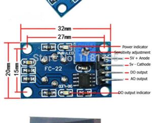
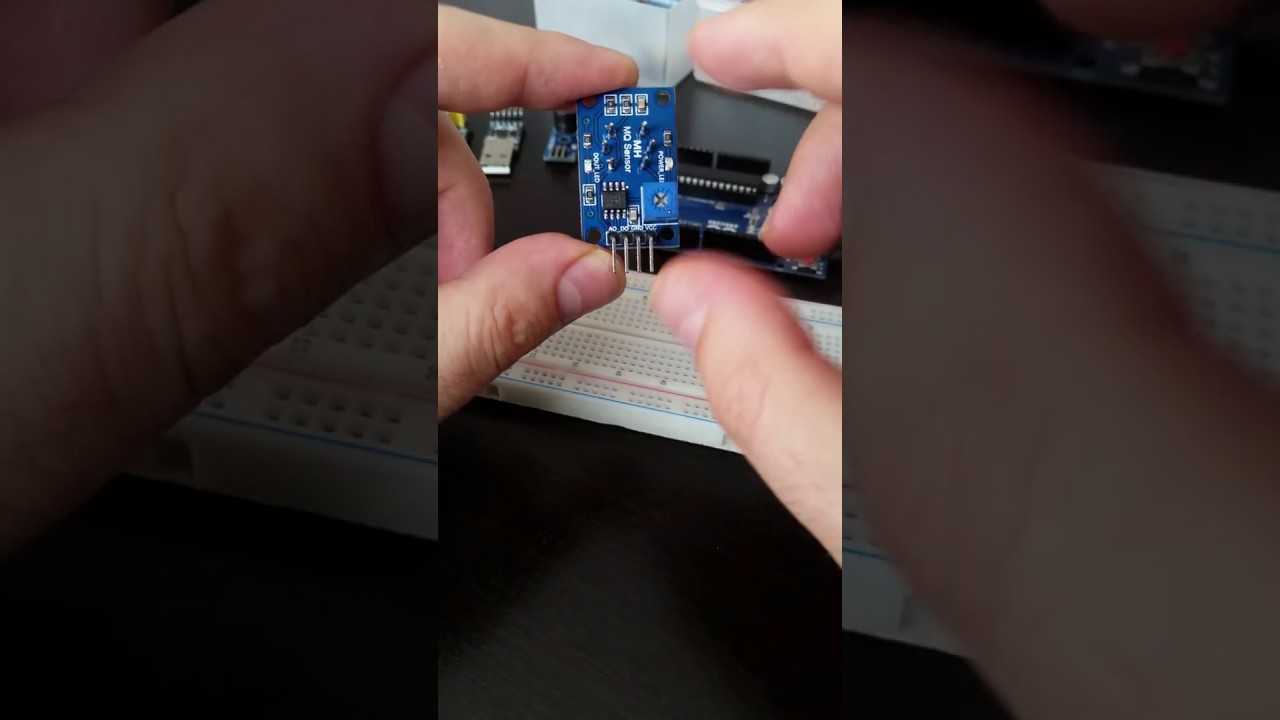
The sensor is quite small and can be fitted easy in any prototype with 4 screws in the board corners. This version comes with a rotating lever from which you can adjust sensitivity by rotating it left or right. On each lateral edge you can find two LEDs which indicates power availability and digital output status. Open this link to read datasheet.
I will come back with more feedback after checking behavior in my house. Until then, thank you for your time.
Hoping that this article inspired you, i kindly invite you share this article, subscribe my YouTube channel and join the communities on social networks. Feel free to comment or send suggestions / remarks so i can improve the content quality.


does this formula work for MQ-8?
Hi Josh, honestly I don’t think it will work, MQ-8 is a H2 Hydrogen sensor, a gas which needs different chemical reactivity. Formulas should be adapted considering the producer datasheet specifications.
Hi GeeksTips,
the load resistance “RL” in this module is 10kΩ? Because you used 10k in the sketch.
RS_gas = ((5.0 * 10.0) / sensor_volt) – 10.0; //Get value of RS in a gas
Greetings from Brazil.
The load resistance is 1k.
Reference:
http://www.dientu4u.com/upload/fckeditor/mach-mq2.jpg
can you explain me 2 of this ?
sensor_volt = sensorValue * (5.0 / 1023.0); //Convert average to voltage
RS_air = ((5.0 * 10.0) / sensor_volt) – 10.0; //Calculate RS in fresh air